If you’re looking for engineering bid specifications to use for your upcoming truck scale bid, please see below for the specifications and some general thoughts and recommendations.
Engineering Specification for Low Profile Steel Deck Truck Scale
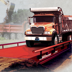
The following set of specifications will describe a fully electronic, low profile, modular type steel deck truck scale system, designed to be optionally mounted on an above grade pier, floating slab or pit type foundation. Scale shall be a 3-module 4-section system that is suitable for easy movement from one location to another.
1.0 General Provisions – Truck Scale
The scale will be a fully electronic, low profile, steel deck design truck scale. The scale platform shall be designed and manufactured in the United States of America. The scale platform, load cells and digital indicators shall be assembled in the United States of America. The scale shall be a Rice Lake Weighing Systems Model 7011-ST-100-OTR or equivalent that will meet the following minimum standards.
1.1 The scale shall have a capacity of 135 Tons (270,000 lb) with a displayed resolution of 200,000 lb x 20 lb in accordance with NIST, Class IIIL devices.
1.2 Scale shall be a fully electronic design. The scale weighbridge will consist of factory welded modules having a total longitudinal span of 70 ft (69 ft 10.5 in) and platform width of 11 ft (10 ft 10.5 in). No field assembly or welding will be allowed. Mechanical lever systems are not acceptable.
1.3 Each scale module shall be designed with a Concentrated Load Capacity (CLC) of 50 Tons (100,000 lb), as defined by NIST. When the CLC is applied at midspan on a module, according to NIST regulations, the maximum stress of the steel shall not exceed 26,500 PSI as determined by Finite Element Analysis (FEA) software. The deflection at this loading condition shall not cause the scale to exceed the allowable accuracy tolerance as specified by NIST in Handbook 44.
1.4 The scale provided will have an unobstructed weighing surface of 11 ft (10 ft 10.5 in) wide by 70 ft (69 ft 10.5 in) in length and a 16.5 in minimum profile. A minimum clearance of 4 in shall be provided between the concrete floor and the bottom of the weighbridge.
1.5 The scale modules will be designed as such to eliminate use of grout plates requiring setting and leveling prior to arrival of the scale at job site. A maximum of 2 drilled anchors (3/4 in x 7 in) will be provided for each load cell stand.
1.6 The scale system shall be a full electronic design, with internal self-checking weigh-bridge. Weighbridges using bumper bolts, externally fixed check rods, or embedded bumper plates in the end walls will not be permitted.
1.7 Minimum weighbridge thickness will be 12 in. Scale shall be an open bottom design. Weighbridges that utilize a sealed bottom plate for structural strength shall not be permitted.
1.8 A 5/16 in diamond checkered steel treadplate shall be supported with a minimum of (12) 12 in wide flange, 14 pounds per foot, structural longitudinal beams, welded to top flange of beam and module end plate. Only structural wide flange beam construction shall be allowed. Weighbridge designs utilizing junior beams or bent plate shall not be permitted.
1.9 The entire bridge assembly shall be cleaned prior to the addition of any coatings or paint to the weighbridge modules. Customer reserves the right to inspect the steel surfaces prior to application of any coatings to the prepared steel surfaces. All steel surfaces shall be free of all welding gases, residue, oil, mill scale and rust.
1.10 All non-visible steel shall be evenly spray coated with an asphalt emulsified coating or have equal protection applied.
1.11 All steel elements shall be steel shot blasted to SSPC-A-SP6 standards.
1.12 All visible steel surfaces will receive a 3-5 mill application of a high solids urethane primer and a high solids acrylic urethane top coat to a finish of 2-3 mill thickness.
1.13 Module end plates shall be a minimum ¾ in thick, and shall be reinforced on each side with longitudinal I-beams. Load cell pockets shall be constructed of ¾ in steel plate and shall be tied to the end plates using tabs and laser cutouts. Scale modules using flat welded or bolted end boxes shall not be allowed.
1.14 The scale will be NTEP Certified and shall meet the requirements set forth by the NIST Handbook 44 for Class III-L devices. The bidder shall submit a current copy of Certificate of Conformance (COC) with bid.
1.15 Structural steel elements will have a combined minimum weight of 30,800 pounds.
1.16 Access covers to the load cells shall be from the top of the scale and shall be boltless in design. Cover plates will be reinforced to adequately handle axle traffic over the covers and will be kept in place with ½ in diameter x 1 in long steel dowels. Cover plates utilizing bolts of any type shall not be permitted.
1.17 A ½ in diameter steel rock guard shall be welded to the end modules.
1.18 The truck scale shall be provided with a fabricated cleanout area measuring
12 in x 84 in with removable end plates at each end of the scale system.
(Optional)
1.19 Manhole frame and cover (24 in square) shall be provided for access to the pit area beneath the scale. (Optional for pit installations)
1.20 Scale shall be equipped with optional gusseted bolt-on safety guiderails on each side of the scale with a minimum of 4 in diameter pipe. A minimum of 3 bolts will be used at each gusset to attach side rail. Guiderails welded to weighbridge shall not be permitted.
1.21 The scale provided shall be a Rice Lake Weighing Systems SURVIVOR® Series Model 7011-ST-100-OTR or equivalent.
2.0 Load Cells and Junction Boxes
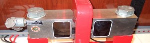
Load cells are rigidly mounted utilizing a single link suspension to provide equal and consistent and evenly distributed force to the load cell. Load cells are totally self-contained, and come complete with mounting stands, single-link suspension, and 60 ft of cable to junction box. Compression or rocker style load cells shall not be permitted.
2.1 Load Cells shall be rigidly mounted in fabricated steel stands parallel to traffic
flow. Suspension system will be E4340 material forged single link suspension
hardened to Rockwell “C” 40-45 to allow self-centering and free floating platform. Rocker column or compression type load cells requiring check rods, anti-rotation pins or bumper bolts will not be permitted.
2.2 Load cells will be of the analog type and have a minimum capacity of 75,000 lb each with an overload safety factor of 150 percent. Scales utilizing a lower capacity load cell than 75,000 lb will not be permitted.
2.3 Scales utilizing adjustable bumper bolts or embedded plates in the wall to minimize movement of the bridge shall not be allowed.
2.4 Systems utilizing proprietary, internal circuitry to convert analog to digital conversion of the load cell signal within the load cell shall not be permitted.
2.5 All access to load cells will be from the top of the scale through formed boltless steel access panels. Covers should be form fitted and should be accessible without use of tools.
2.6 Steel conduit will be provided within the weighbridge for load cell cable runs.
2.7 A flexible screw-type conduit fitting shall be provided at each load cell. Load cell cable shall be totally enclosed within permanent conduit provided within the weighbridge. Load cells using connectors of any type will not be permitted. Braided metal cable covering shall not be used in place of steel flex conduit or hardened steel conduit.
2.8 Load cells shall be of 4340 alloy steel nickel plated and shall be sealed with a minimum IP67 rating.
2.9 Load cells shall be non-proprietary in design, including both mechanical operation and electronic transmission of data. Manufacturers using proprietary load cell technology available from a single source will not be permitted.
2.10 Replacement load cells shall be available from a multitude of vendors nationally, and shall not be single sourced or of a proprietary design.
2.11 Fiberglass Reinforced Polyester (FRP) junction box with formed contoured edges and gasketed top access. Junction box shall have a GORE-TEX® single directional membrane vent. Steel junction boxes shall not be permitted.
2.12 Load cell stands will be flush mounted to concrete piers and anchored using wedge locks or similar bolts. A maximum of (2) ¾ in x 7 in anchor bolts will be required per stand and will be included in the cost of the scale. Grout plates or embedded items in the foundation concrete will not be allowed.
2.13 A 1 in braided copper transient bypass cable shall be provided at each load cell from the weighbridge to the base stand.
2.14 UPS Duplex Voltage regulating transformer, or equivalent.
2.15 UJB-3T6 DC Transient circuitry protection or equivalent.
2.16 Load cells shall be warranted for a minimum of five years against failure of all types, including lightning or surge voltage.
2.17 A single-point grounding system will be provided. Systems utilizing a multiple point ground will not be permitted.
3.0 Digital Instrumentation Specifications
The scale instrument shall be a Rice Lake Weighing Systems 1280 Enterprise™ Series
programmable indicator/controller complete with operator-friendly diagnostics for load cells and digital j-box or equivalent.
3.1 The scale instrument shall be NTEP Certified and meet or exceed all specifications set forth by NIST Handbook 44 for Class II, III, and IIIL devices. Additionally, the instrument shall meet or exceed approvals for UL, C-UL and CE. The manufacturer, on request, shall provide a Certificate of Conformance (COC) to these standards.
3.2 The scale instrument shall be housed in an all stainless steel 304, IP69K enclosure measuring 10.85″ wide x 12.50″ high x 5.25″ deep.
3.3 The instrument shall be 100 percent manufactured by the manufacturer of the
weighbridge assembly.
3.4 The instrument shall be Linux® based
3.5 The scale instrument shall be fully programmable and configurable according to the needs of the application.
3.6 The scale display shall be a LCD graphical, color display with minimum size of 800 x 480 pixels and be available in 500 or 1,000 NIT.
3.7 The instrument shall allow connection of a QWERTY-type, computer-style keyboard.
3.8 The front panel of the instrument shall have the following operational keys as standard with tactile feedback:
• Zero
• Print
• Gross/Net
• Clear
• Tare
• Decimal Point
• Units
• Numeric 0-9
3.9 The instrument shall have the following displayed operational annunciators: gross, tare, net, zero, motion and three units of measurement
3.10 The scale instrument shall have the capability of powering up to (16) 350 Ohm load cells.
3.11 The instrument shall have the ability to display both gross and net weights and the ability to recall gross or tare weights in the net mode.
3.12 The instrument shall have the ability to provide in/out, gross/tare/net calculation of individual truck weights and storage for the following information:
• 1,000 open transactions
• 1,000 tare weights
• Database report
3.13 The instrument shall have six smart card slots for additional scale channels, serial ports, digital inputs and outputs, analog outputs and protocol interfaces.
3.14 The instrument should have 100 setpoints, 18 configurable setpoint types.
3.15 The scale instrument shall be designed to provide noise protection for RFI, EMI and ESD.
3.16 The excitation voltage shall be 10 +/- 0.5 VDC.
3.17 The instrument shall have an automatic zero tracking feature that will be programmable and in compliance with NIST, Measurement Canada and OIML regulations.
3.18 The instrument shall be fully programmable.
3.19 The instrument shall include as standard surge voltage protection as recommended by the manufacturer
3.20 The digital instrument shall be warranted by the manufacturer for two years from date of installation.
3.21 The instrument shall have a multi-level digital filtering system for environmental noise or vibration.
3.22 Individual load cell monitoring and system diagnostics shall be available when paired with the iQUBE2® digital diagnostic junction box.
3.23 The scale instrument shall have an internal resolution of 8.000.000 counts.
3.24 Operating temperature for the instrument shall be -4°F to 131°F (-20°C to 55°C).
3.25 Customized programmable print formats, including 20 auxiliary print formats, shall be available.
3.26 Operational power input shall be 115 or 230 VAC, ±10 percent. 50/60 Hz single phase.
3.27 The scale instrument shall have the capability of receiving custom programs.
3.28 The instrument shall have a real-time clock and battery-backed feature.
3.29 A/D conversion rate shall be selectable from 7.5 Hz to 960 Hz.
3.30 Multi-range/internal selection for setting two or three weight ranges with different division sizes
3.31 The digital instrument should have web server capabilities.
Before You Send out Your Truck Scale Bid or Proposal
We hope these truck scale engineering specs will help you with your next truck scale bid or project. There are a couple of points we wish to mention. Obviously, these truck scale bid specs are created in a way to assist the manufacturer who originally created the specifications. In this example, the Rice Lake OTR would be the benefactor. But truthfully most all truck scale manufacturers create these specifications and word them in a such a way that it makes it difficult for other scale manufacturers to meet their guidelines.
There are several points in here that are worth mentioning. For example, under load cells, the specs say compression or rocker style load cells shall not be permitted and they mention rocker column or compression type load cells requiring check rods, anti-rotation pins or bumper bolts will not be permitted. That eliminates several competitors right there. Look we aren’t engineers but we have some truck scales that we offer which include these types of cells and they do quite well.
Another item mentioned is replacement load cells shall be available from a multitude of vendors nationally, and shall not be single sourced or of a proprietary design. This is very important. In our opinion this is a key point to think about when you design your truck scale. If you choose a system that only has one vendor or supplier who can assist you it could be trouble if there is ever a problem with supply chain issues. This is one concern we have sometimes with certain manufacturers and certain technologies like digital and hydraulic.
Finally we have to mention the scale indicator. The specs above mention some of the following. The scale instrument shall be a Rice Lake 1280 Enterprise Series
programmable indicator/controller. The scale instrument shall be housed in an all stainless steel 304, IP69K enclosure measuring 10.85″ wide x 12.50″ high x 5.25″ deep. The instrument shall be 100 percent manufactured by the manufacturer of the weighbridge assembly. The digital instrument should have web server capabilities. All of this is nice but in many truck scale bids, you simply don’t need all of this.
For example, why do you need a stainless steel truck scale indicator that is a specific size and IP69k washdown rated? In most cases, the indicator is simply going to sit in your perfect 72 degree scale house beside your computer and ticket printer. So in most situations you do not need an expensive weight indicator like this.
Our recommendation would be to take the best of from this list of truck scale specs to create your ideal truck scale request for bid proposal. Then you can send those bid requests out to local scale companies that you trust. Don’t forget we’ve discussed what to look for when buying a truck scale before along with truck scale prices and the disadvantage of working with a scale company that basically only sells one brand of scales. Contact our heavy capacity sales department when you’re ready to proceed by calling (919) 776-7737